How to Convert ER Diagram to Relational Database
The ER Model is intended as a description of real-world entities. Although it is constructed in such a way as to allow easy translation to the relational schema model, this is not an entirely trivial process. The ER diagram represents the conceptual level of database design meanwhile the relational schema is the logical level for the database design. We will be following the simple rules:
1. Entities and Simple Attributes:
An entity type within ER diagram is turned into a table. You may preferably keep the same name for the entity or give it a sensible name but avoid DBMS reserved words as well as avoid the use of special characters.
Each attribute turns into a column (attribute) in the table. The key attribute of the entity is the primary key of the table which is usually underlined. It can be composite if required but can never be null.
[info]It is highly recommended that every table should start with its primary key attribute conventionally named as TablenameID.[/info]
Taking the following simple ER diagram:
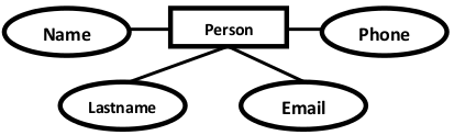
The initial relational schema is expressed in the following format writing the table names with the attributes list inside a parentheses as shown below for
Persons and Phones are Tables. name, lastname, are Table Columns (Attributes).
[info]personid is the primary key for the table : Person[/info]
2. Multi-Valued Attributes
A multi-valued attribute is usually represented with a double-line oval.

If you have a multi-valued attribute, take the attribute and turn it into a new entity or table of its own. Then make a 1:N relationship between the new entity and the existing one. In simple words. 1. Create a table for the attribute. 2. Add the primary (id) column of the parent entity as a foreign key within the new table as shown below:
Phones ( phoneid , personid, phone )
[info]personid within the table Phones is a foreign key referring to the personid of Persons[/info]
3. 1:1 Relationships
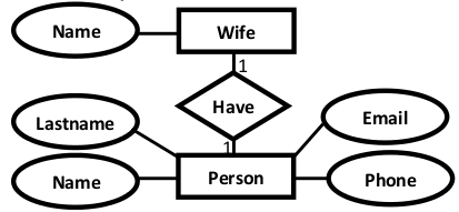
To keep it simple and even for better performances at data retrieval, I would personally recommend using attributes to represent such relationship. For instance, let us consider the case where the Person has or optionally has one wife. You can place the primary key of the wife within the table of the Persons which we call in this case Foreign key as shown below.
Wife ( wifeid , name )
Or vice versa to put the personid as a foreign key within the Wife table as shown below:
Wife ( wifeid , name , personid)
[info]For cases when the Person is not married i.e. has no wifeID, the attribute can set to NULL[/info]
4. 1:N Relationships
This is the tricky part ! For simplicity, use attributes in the same way as 1:1 relationship but we have only one choice as opposed to two choices. For instance, the Person can have a House from zero to many , but a House can have only one Person. To represent such relationship the personid as the Parent node must be placed within the Child table as a foreign key but not the other way around as shown next:
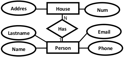
It should convert to :
House ( houseid , num , address, personid)
5. N:N Relationships
We normally use tables to express such type of relationship. This is the same for N − ary relationship of ER diagrams. For instance, The Person can live or work in many countries. Also, a country can have many people. To express this relationship within a relational schema we use a separate table as shown below:
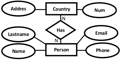
It should convert into :
Countries ( countryid , name, code)
HasRelat ( hasrelatid , personid , countryid)
Relationship with attributes:
It is recommended to use table to represent them to keep the design tidy and clean regardless of the cardinality of the relationship.
Case Study
For the sake of simplicity, we will be producing the relational schema for the following ER diagram:
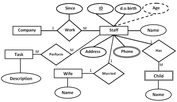
The relational schema for the ER Diagram is given below as:
Staff( StaffID , dob , address , WifeID)
Child( ChildID , name , StaffID )
Wife ( WifeID , name )
Phone(PhoneID , phoneNumber , StaffID)
Task ( TaskID , description)
Work(WorkID , CompanyID , StaffID , since )
Perform(PerformID , StaffID , TaskID )
[info]There are some errors above ? please use the comment box to let us know[/info]
About Author
by Imed Bouchrika
Dr. Imed Bouchrika received his PhD degrees in Electronics and Computer Science from the University of Southampton in United Kingdom in 2008. He has been in the industry as a software developer for over a decade primarily designing and developing interactive web applications. At the same time, he worked as a research fellow at the Image Processing research group at the University of Southampton investigating the potential use of gait as new biometric for forensic and security applications.
Leave a Reply to Finals Thomas Cancel reply
-
 Motivations of why to Learn Databases
-
 List of Recommended Websites to Learn Databases
-
 BaseX : Tutorial for using an XML Native Database Management System
-
 Making Connection to Oracle Database System with Java
-
 Oracle : Type/Object Creation, Inheritance and Method Implementation with Examples
-
 Tutorial for how to Get started to learn Oracle
As you said that there are errors:
1. Wife ( WifeID , name )
2. Task ( TaskID , description)
Both must have Staffid otherwise it doesn’t represent the relationship
Married(Wifeid, Staffid, Certificate_No)
This must be the additional info…
how to translate ER diagram of banking database to relation.
pls reply immediately with a breif explanation and appropriate example for banking database relation.
thanks for this wonderful article, buh in the case study, the ER diagram implies that its just men that work in the company used. so I think it will be better you use Spouse as the entity set where you used Wife. its just me suggestion.
very very thanks.
very good site to learning database and ER diagram
What about company and staff relation?
Howdy! I could have sworn I’ve been to this site before but after browsing through many of the posts I realized
it’s new to me. Nonetheless, I’m certainly
happy I came across it and I’ll be bookmarking it and checking back
frequently!
Thank you so much 🙂